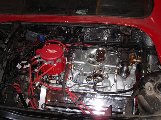
First engine start!
Even though I expected it to start, I was a bit surprised how quickly it fired up. I think there was a fair bit of gas in some of the cylinders from playing around with the carbs and this might explain the puff of white smoke from one of the tail pipes (unburned gas). It very quickly cleared up. The engine did start smoking quite a bit from the rear cylinder bank. This was just the paint burning off from the header reducer (welded to the exhaust pipe where the pipe bolts onto the header). Very cheap paint was used on this and it burned off pretty quickly. I had a good look at everything after the run and there was nothing else burned or discoloured. I only ran it for 10 seconds or so, just to make sure it would run. There were no fluid leaks underneath -- a miracle.
This is a video of the first start. Yes, it is the very first attempt at starting the engine since this project began over 1 1/2 years ago:
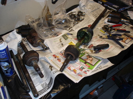
This is a really messy job, working with the axles and constant velocity joints. There are various axles here, some from a manual tranny Fiero and some from an auto tranny Fiero. The manual tranny ones are a little larger in diameter, so they are a better choice. Of course the length of the axles may not match up with what I need for my installation, so I'm taking them apart and mixing and matching what I have to see if I can get a combination that will fit. It is really disgusting digging all the old grease out to get at the snap rings that hold the ends on. Of course things are complicated by using the 4T65E-HD tranny which has a larger spline on the passenger side than the Fiero tranny. So you use the "tripot" from the tranny, and the axle pieces from the Fiero and hope it all fits. I think I have one side that will work. I'll know better when I get it cleaned up, re-greased, and put back together.
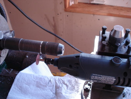
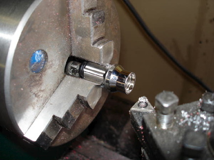
Through a lot of research, measuring, and calculating, I found that a passenger side axle from a Pontiac Grand Prix GTP (the one with the 3.8 supercharged engine and the same tranny I am using) is almost the right length for my application. I took the CV joints apart to leave the bare axle. It was just a little too long, by around 1/2". So I figured the easiest thing to do was to cut a new snap-ring groove in the spline and then cut 1/2" off the end of the shaft. As it turns out this was not so easy as the splines are hardened and I couldn't cut it on the lathe. I mounted a small grinder on the tool post, with a thin cut-off wheel, and used that to cut the new groove. I then used the larger air cut-off tool to cut off the end of the shaft. You can see the spline is long enough to allow for the 1/2" relocation of the groove. I maybe could have left the groove where it was, but the CV joint was coming very close to bottoming in the tripot, so the axle was just marginally too long.
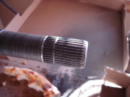
The new groove, the old groove, and the axle shaft cut off about 1/2".
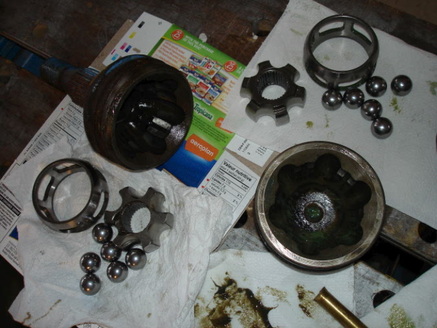
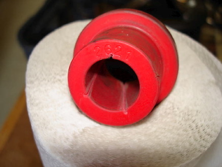
Just to further confuse things. The Fiero axles come in 2 sizes (sizes being the thickness of the axle, as they also come in various lengths for the driver or passenger side of manual and automatic cars). The auto tranny axles are thinner than the manual tranny ones, so it is a good idea to try and use the manual tranny ones. The splines on the ends of the axle shaft are also larger on the manual tranny axles and so are the CV joints that fit on these splines. What I discovered after shortening the GTP shaft is that the GTP shaft has a spine on the end that is slightly larger again than the manual Fiero axle. Fortunately, the only part that is different between the manual Fiero CV joint and the GTP CV joint is the inner race; the star shaped part shown in the picture. So I took apart the Fiero CV joint and the GTP CV joint and basically rebuilt the GTP parts into the Fiero tripot (can't use the GTP tripot on the outer end of the shaft since it is too big to fit into the Fiero wheel bearing). I put everything together and it fit perfectly!
For the driver's side axle, I used a '95 Beretta auto tranny passenger side axle, and swapped the inner CV joint and tripot with manual tranny Fiero bits. Like I said, a lot of research to find the right combination of parts that fit together and give the right length. So now I have both axles almost done. I've trial fitted both of them without greasing up the inner tripot, so now I've removed them so I can grease them and install the rubber boots. Then I will finally be done with all this greasy mess!
For the driver's side axle, I used a '95 Beretta auto tranny passenger side axle, and swapped the inner CV joint and tripot with manual tranny Fiero bits. Like I said, a lot of research to find the right combination of parts that fit together and give the right length. So now I have both axles almost done. I've trial fitted both of them without greasing up the inner tripot, so now I've removed them so I can grease them and install the rubber boots. Then I will finally be done with all this greasy mess!
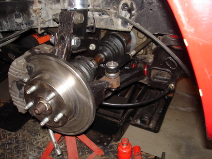
Here is the driver's side axle installed; CV joints packed with grease and the rubber boots clamped on. So the suspension is finally back together. Since the Fiero used many parts from existing cars, it used rear suspension pieces from the front of an existing car (Chevette I think). That is why you see what looks like a tie-rod, normally used for steering, here on the rear suspension. It ties to a point on the frame. Handy way to adjust the rear toe. Rusty brake line still there.
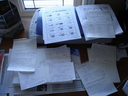
This shows all my notes and calculations I did to figure out the right axles to use to make it all fit.
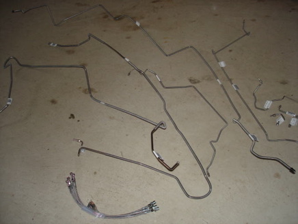
OK, enough of those rusty, horrible looking brake lines. This is a set of pre-bent stainless steel ones and transmission cooler lines. Also there is a set of flexible stainless steel lines for each corner of the suspension. Since I'm replacing most of the braking system, I might as well do it right and replace it all; just a matter of time before one of the existing rusty lines breaks.
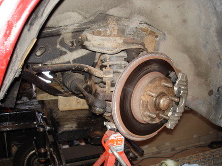
Skipping ahead here, the new brake lines are installed, at least to the rear of the car; this is the passenger side rear suspension. It was pretty easy removing the old lines, especially when you don't need them. Just cut them off from the connection points (like the splitter shown in the picture), then take the piece to the bench to take the old fittings off.
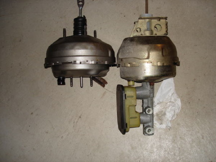
As long as I am replacing every piece of the braking system (except the pedal!), I'll replace the power booster as well. Actually there is another reason I am replacing it. The Fiero is known for having brakes that are OK, but a bit weak by today's standards. There are a lot of ways of upgrading them (larger rotors, calipers, etc). Replacing the booster with a larger one is an easy way to improve the brakes. The Fiero booster, with the master cylinder attached, is shown on the right. The one on the left is from an Chevy S-10; it is larger in diameter which will give more braking pressure for the same pedal force. It does fit in place of the Fiero unit with a few hammer blows to the surrounding sheet metal.
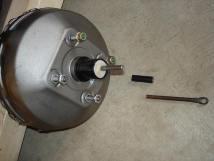
Of course nothing is ever that easy. The rod that goes from the brake pedal is longer on the Fiero unit, so the S-10 rod is cut off and part of the Fiero one attached. Since you can't take the booster apart, you have to be careful not to put too much heat into it when welding. I machined a piece of tubing to fit over the rod ends, and then just tack-welded the rods to the tube, making sure the overall length was correct.
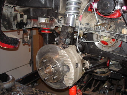
This is the front suspension. I have new rotors and wheel bearings that haven't been installed yet. I pulled the brake lines off and then decided to take the whole suspension assembly apart. A while back I bought a kit that converts it to an adjustable coilover setup (like the rear suspension) and also replaces the upper and lower control arms with tubular units. Might as well pull it all apart now and finish it rather than just do the brakes now, and then take it all apart later.
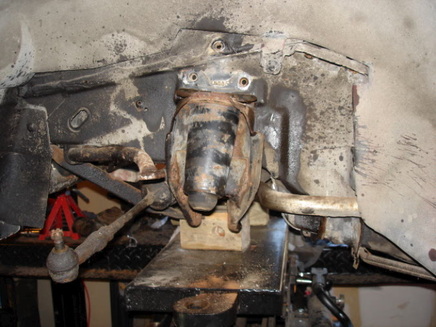
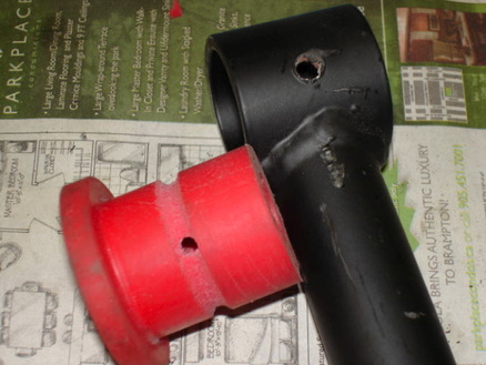
After a certain amount of effort and cursing the rusty bolts that likely haven't been taken apart in 25 years, it's apart. Still more work to be done on it though, since some of the metal has to be cut away. The large cylinder looking thing with the rubber on the lower end has to be removed for clearance (this is the bump-stop and the existing coil spring guide tube). Also some of the sheet metal just above that has to be cut away.
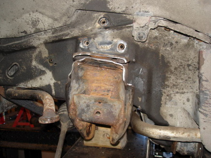
Modifications done. Combination of air cut-off wheel and saw, and the requisite cursing at appropriate times, and the excess metal is gone. A little cleaning and painting and it will be ready to put back together with the new components.
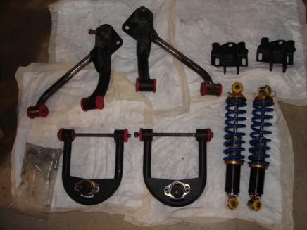
These are the various pieces that will replace the factory Fiero stuff. Tubular upper and lower control arms with polyurethane bushings and adjustable coilover shocks/springs. The person I bought them off had never used them, but had modified the lower control arms to fit a different application. The thinner of the 2 arms has been modified, so I'll have to cut them and reweld them back in the proper location to fit the Fiero frame.
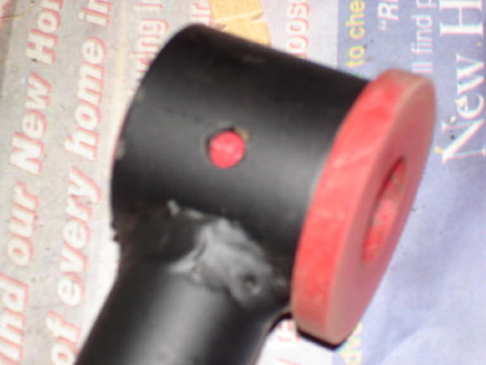
A little out of focus, but here is the issue with the suspension arm. This is the upper control arm, as supplied, with the polyurethane bushing. Now it's nice that a threaded hole is provided for a grease fitting, but the movement is between this bushing and a steel sleeve that goes inside it. No way the grease is going to get to where the movement is.
Here is my solution. Cut a groove around the bushing and added some holes for the grease to travel to the inner steel sleeve. The groove is in case one of the feed holes doesn't happen to line up with the grease fitting, the grease will still find it's way in.
I also added some small grooves so the grease can get into the interface between the bushing and the steel sleeve. Also, the fit of the steel sleeve was so tight that it had to be hammered in. I thought this was a little too tight so I took each one out and machined the outside diameter of the steel sleeve a little to reduce the interference fit. I greased everything up and put the control arms all back together. Oh, I cut and rewelded the lower arms to match the geometry of the mounting points on the car.
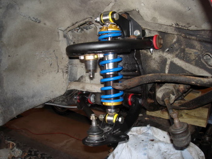
Partially assembled. Nice new parts, eh? The new upper shock/spring mount is bolted in and the upper and lower control arms are installed. The coilover shock assembly is fitted, and now the spindle that goes between the upper and lower ball-joints is ready to be installed (as soon as I clean it up a little and take off the old disc brake and wheel bearings). This is showing the passenger's side of the suspension; I'm working on both sides at the same time.
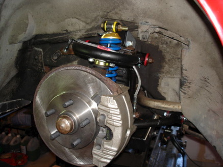
This shows one side almost finished. The only thing left is to put on the wheels (which I just got tires for, so I can see what it is finally going to look like on the proper wheels). I did buy the aluminum wheel spacers, which have to go on first.
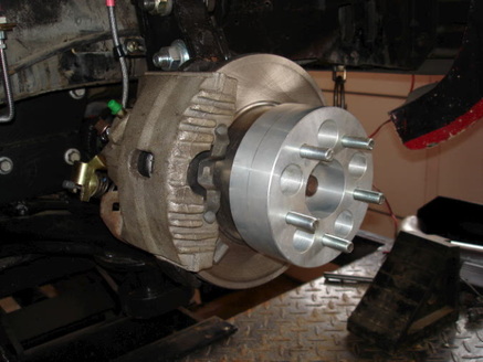
This is the rear suspension with the 2" wheel spacer. The fronts get 1" spacers.
One small problem with fitting the wheels. Since I am using spacers, the proper lug nuts to go with them have the usual tapered seat that sits on the wheel. They also have the short section of "tube" that fits in the hole in the wheel to help align things. The problem here is that the portion of the lug nut that goes into the wheel didn't fit. It was about .025" too large on diameter, so I had to machine each lug nut down a little bit to fit into the hole in the wheel. A bit tedious, but it did go fairly quickly once I had the lathe set up to take the right amount off in one pass.
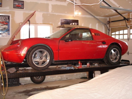
Finally it is on its real wheels and tires! I think these wheels really suit it nicely.
Looks like it is almost ready for the road. Well, maybe it is at least ready for a quick test drive?
Looks like it is almost ready for the road. Well, maybe it is at least ready for a quick test drive?