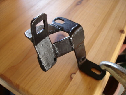
What the heck could this be?
This is the throttle bracket I welded-up from strip stock. It bolts to the carb mount and a boss on the intake manifold. The 2 slots allow it to be positioned back and forth to make sure the throttle is closed when there is no pressure on the gas pedal. The square hole is for the plastic end of the Fiero throttle cable to snap into; tricky drilling a square hole! The small drilled hole is for a throttle return spring.
This is the throttle bracket I welded-up from strip stock. It bolts to the carb mount and a boss on the intake manifold. The 2 slots allow it to be positioned back and forth to make sure the throttle is closed when there is no pressure on the gas pedal. The square hole is for the plastic end of the Fiero throttle cable to snap into; tricky drilling a square hole! The small drilled hole is for a throttle return spring.
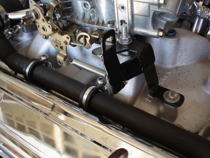
Here you see it installed with 1 throttle return spring on it. There is another return spring attached to the opposite end of the throttle lever on the carb; you can see that one going forward.
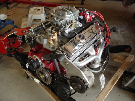
Here is the engine dressed and almost ready to go into the car for the final time (I hope!). You can see the water pipe hooked up to the thermostat housing. You can see the 'T' fitting and elbow I added to the heater water outlet; the top of that 'T' will have the temperature sensor screwed into it. The electric water pump is mounted here, but it has to come off to install the engine. You can see the fitting that I made up that is attached to the inlet of the pump. The large opening will hook up to the pipe leading in from the lower rad hose and the smaller fitting, down low, will take the return water from the heater core. I've also run the spark plug wires. The best way to keep them away from the header pipes was to run them underneath and bring them up the rear. On the opposite side, some run under and some run over the header, whatever keeps them away from the header pipes.
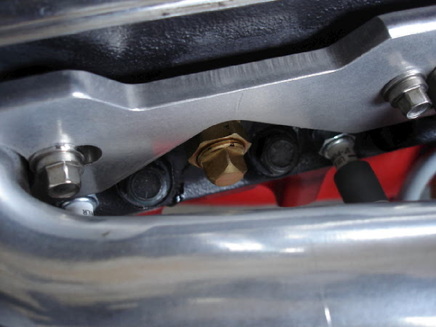
On the Chevy engines, there is a port on the head between the #1 and #3 cylinders that leads into the water jacket. This is sometimes used for the water temperature sensor. I found that it came too close to the headers when I tried putting the sensor on it, so I plugged it and am using the one on the intake manifold.
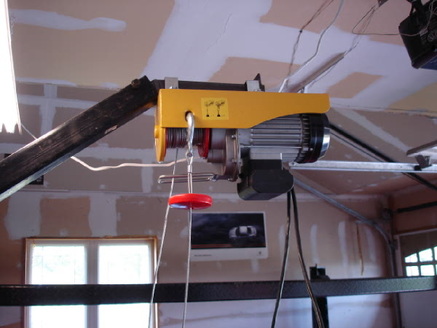
Since the engine has been in and out dozens of times now for various trial fits, this arrangement makes it much easier to hoist the engine. With the Fiero, you want to be at the front of the cradle while the engine is being hoisted in so you can line up the front attachment points with those on the frame of the car. Normally to raise and lower the engine you have to be back at the hoist. So you find yourself raising the hoist a little, taking a look at the front cradle mounts, going back to the hoist to make a small adjustment...and on and on. I picked up one of these electric winches on sale (at Princess Auto), and made a bracket to mount it to the engine hoist. This makes it very easy to maneuver the engine in and out since you control it with the electric control with one hand while guiding the cradle/engine with the other hand. You just leave the hydraulic arm of the hoist all the way up.
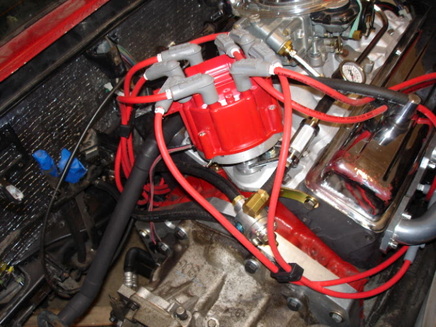
OK, so the engine is back in, maybe for the final time. You never really know when it is the final time, but I hope I haven't forgotten anything that I can't get at with the engine in place. This shows the fuel system connections. One line comes from the tank into the pressure regulator. One line goes from the regulator to the filter and then the carb. The return line takes the excess fuel back to the tank.
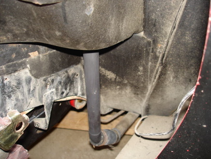
This is the water pipe connection coming from the rad and down the passenger side of the car. I cut it off and joined it onto one of the copper pipes I made up.
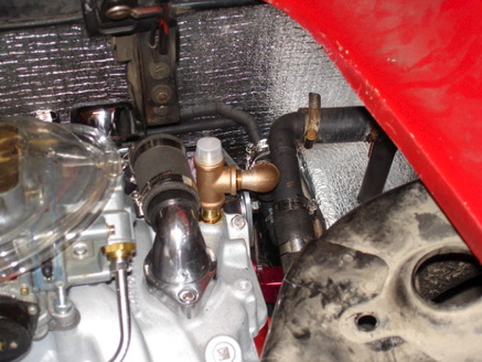
You can see here where the water pipe from the previous picture comes up into the engine compartment and joins with the pipe leading into the water pump. You can also sort of see where the 2 heater pipes join onto the pipes at the front of the engine. The cap on the 'T' fitting will be replaced with the water temperature sensor, once I figure out which one to use; the Fiero had 3 of them and only one is for the gauge. Excuse the rusty looking hose clamp. It was all I had on hand.
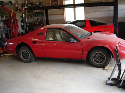
I decided it was time to put the rear suspension together and get the car back on its wheels. So after many, many months, the car is back on its feet! I don't like the big space above the rear wheel and will have to do something about that. These are the 13" wheels that came on the white Fiero.
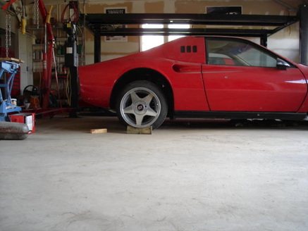
This is what is eventually going to go on the car. These are 16" x 7" wheels. It is just sitting in front of the car here to see what it will look like. Looks good!
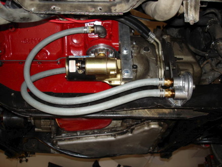
The car was pushed onto the lift to make it easier to work under it. This is the final hookup of the remote oil filter.
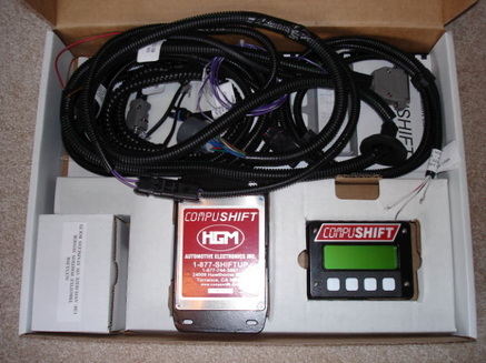
This is what is going to control the transmission. The 4T65E-HD is electronically controlled and the stock Fiero computer can't control it. It basically hooks up to the transmission, battery power, and a sensor on the carb linkage to tell it the throttle position. It also allows manual shifting (tap shift) which might be cool to fool around with.
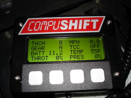
This is the display unit that comes with the transmission controller. This is jumping ahead a bit to when I got it all hooked up and ready for a test. It displays engine RPM, vehicle speed, what gear the tranny is in, the torque converter locked-up activation, battery voltage, tranny fluid temperature, throttle position, and tranny shift pressure. Pretty neat! You can also control the shift RPM and shift firmness with this, and also use it for tap-shifting.
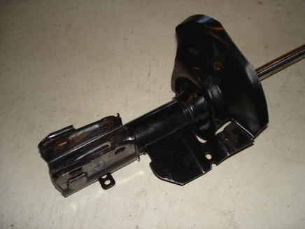
This is one of the rear shock absorbers. The large sheet metal part is the spring seat for the stock Fiero spring. I'm converting these to coilover shocks so the height of the car can be adjusted. Also the spring rate can be changed by swapping out the springs. I'm starting with 325 lbs/in springs, 12" long.
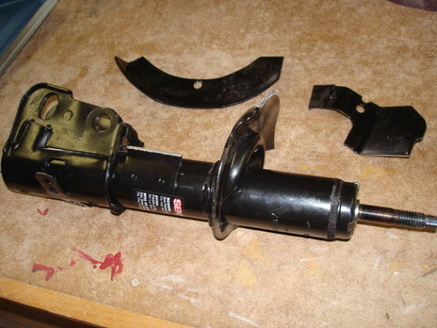
The stock spring seat has to be removed to make these struts into coilovers. A couple passes through the bandsaw removes part of it.
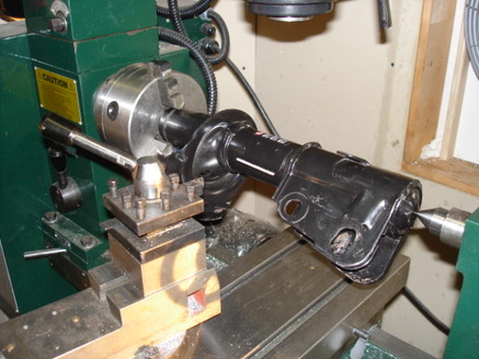
To remove the rest of the spring seat I put the strut on the lathe to machine off the weld where the seat is attached to the strut body. Nice and slow turning since it is just a tiny bit out of balance.
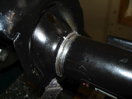
This is the weld machined off. The spring seat can now be slipped off the strut.
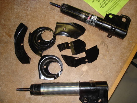
So the stock spring seats have been removed in several pieces. A threaded aluminum sleeve is slid over the strut and a spring seat is then threaded on that to allow adjustment of the spring height.
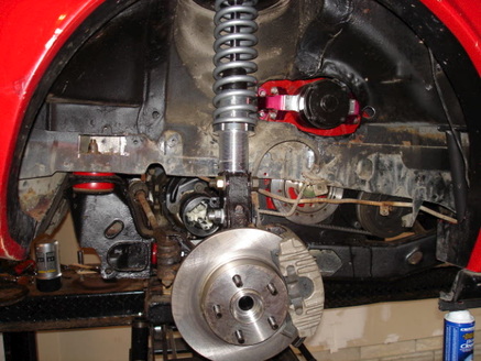
Now does it all make sense? I've skipped a bunch of steps on modifying the upper spring seat, but this shows the assembly in place. You can see the lower spring seat that can be threaded up and down to vary the height of the car. Rusty brake lines still there.
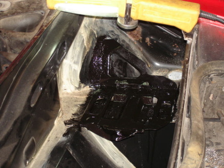
So the suspension is back together again, and the car is on its wheels. This is the Fiero battery tray, modified a little and welded into the trunk. Some people put the battery tray in the front of the car to add some weight there. I wanted the weight in the back, over the rear wheels, to help with traction.