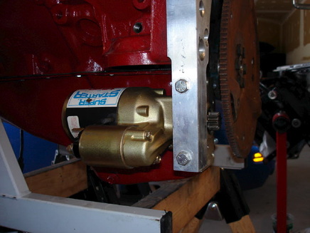
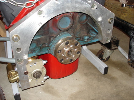
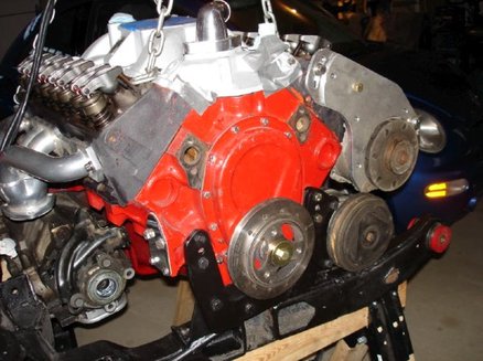
Now onto some finicky stuff. This is the starter motor, fitted to the adapter plate. Normally, the starter on a small block Chevy mounts on the other side of the engine. With this installation, the transmission blocks that area, so the starter has to go here. Of course this is where the oil filter normally sits with the Chevy block, so that has to move too.
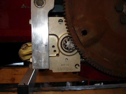
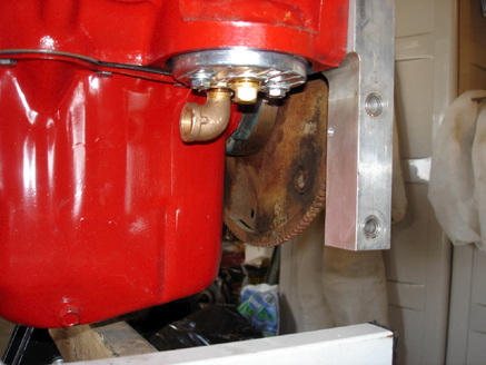
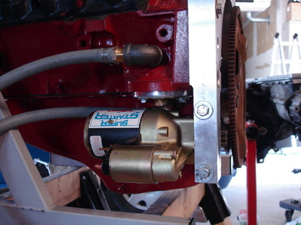
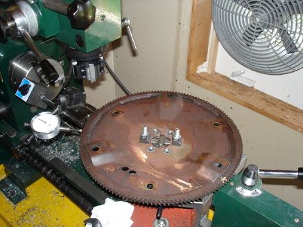
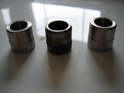
First problem. This starter is really meant to be used with a swap kit using a manual transmission. Since the adapter plate is different with a manual transmission, the starter mounts differently on the two swaps. Since this is what I have, and I don't want to buy the correct one, I'll rework this one to make it work. You can see here that the gear is not engaging properly with the large ring gear. The starter has to be moved farther away from the large gear. Easiest way to do this is to machine some material off the starter mounting block (the gold coloured piece).
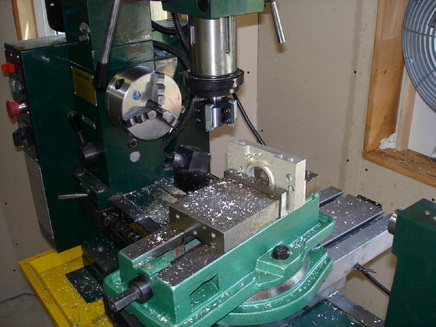
The starter mounting block on the milling machine. It is really a useful thing to have when doing this kind of work. The one I have is a combination mill and lathe. Here I'm taking a little material off and then will trial fit it (and ended up taking a little more off).
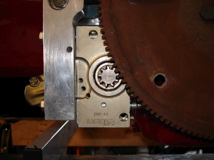
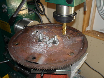
Much better. Good alignment of the 2 gears now. It may not look perfect in this picture, but the bolts aren't tightened up and that will pull it into the correct position.
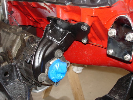
Since the starter goes where the oil filter normally is, an adapter is used with a remote oil filter. The centre hole is plugged, and an elbow is installed that will just clear the starter when it is in place. If it looks kind of like a plumbing fitting, that's because it is.
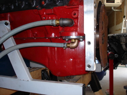
This is what it looks like with the oil lines in place. The hole that was plugged (in the oil filter adapter plate) leads into the same place as the threaded hole in the side of the block, just above the filter housing. So this side location is used for the other hose. Several plumbing fittings make it all work. The other end of the hoses will go to a remote oil filter mount.
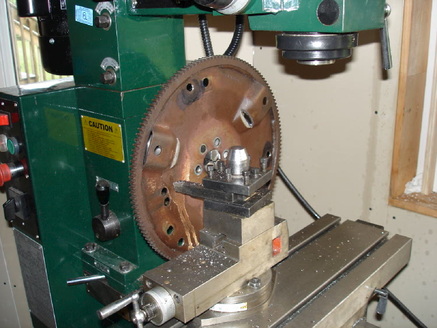
Everything in place with plenty of room. OK, not plenty, but enough. I had to mill a little material off the centre fitting on the oil filter adapter plate to give a little more clearance with the starter. An oil leak is fairly disastrous to the starter motor in this application, so I hope I have everything sealed up well.
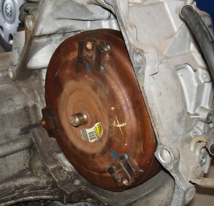
Time to get the transmission mounted up to the engine. Fairly major problem encountered right away. This is the torque converter from the 4T65E-HD transmission. It is a bit larger than the non-HD one, and is also a different shape. Notice how it sort of bulges out as you come in from the bolt holes. Also, the bolt holes are at a slightly larger radius than the other torque converter, so the flexplate will have to be re-drilled for these holes; this is not a big deal...but...
This is the flexplate from the Fiero engine/tranny. Ignore for now that it is mounted on a milling machine, and not the engine. The mounting holes for the torque converter (known from now on as the TC to save me some typing) are the ones on the flat portion, not the raised pads. This normally is not a problem as the TC that comes with the Fiero does not bulge out in the back and is smaller than the one from the 4T65E-HD tranny. If the HD TC is mounted on these pads (which happen for some reason to be at the correct radius) then it will stick too far back and will hit the tranny bellhousing. So it has to be mounted on the flat portion, by re-drilling the holes at a larger radius. The problem is that the pads hit the back of the TC before it sits on the mounting holes. So some of this raised pad area has to be removed.
This was my first attempt at milling off the pads. Since I only have a small rotary table, it wasn't really secure enough and was jumping around a bit when milling.
Fortunately the lathe is large enough to swing this diameter, so this was a better way to do it. Also, it chucked from the centre hole of the flexplate, so it was automatically centred. With the milling, I had to carefully centre it to make sure I wasn't affecting the balance too much. The only concern here is that it is an interrupted cut, so I went fairly slow and stopped often to check the progress. But it did work out nicely.

This is the flexplate with the machining finished. It is sitting on the TC to show that it now sits on the mounting areas and doesn't hit the 3 pads. I drilled 3 mounting holes at the proper radius and cleaned up the machined edges around the areas that were removed.
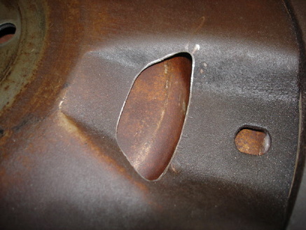
This is a close-up of one of the areas where the pad was partially removed. The edges have been cleaned up and it just clears the TC, that you can see through the opening.
There are 2 dowels pins that align the transmission to the adapter plate. They are drilled out since bolts pass through them. I found that the holes in the adapter plate were a little larger than the ones in the tranny, so the dowel pins were a little loose. I made up some new dowels with a small step so they fit properly in both the tranny and the adapter plate. The "stock" dowel is shown between the 2 new ones.
This is the adapter/spacer that bolts onto the crankshaft (man, there sure are a lot of different adapters!). Since the engine/tranny spacer is fairly thick, this one is needed to space the flexplate back the correct distance into the tranny. The flexplate bolts onto this spacer, the torque converter bolts onto the flexplate, the transmission bolts onto the main adapter plate and, hopefully, it all fits.
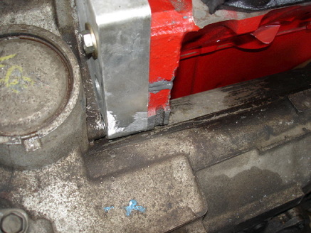
Well, it almost fit. The part of the tranny that comes around the side of the engine was hitting the adapter plate. I just had to take the corner off the adapter plate and then it fit OK. That's the problem with fitting a transmission from a front-wheel drive car to a small block Chevy. The transmission wraps around the side of the engine, which this engine was never designed for. I also trimmed a little off the side of the block, but that was back when I was trying to use the adapter plate for a manual tranny, so I'm not sure if the trimming is needed or not; looking at this picture, I think it is.
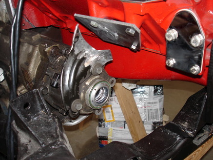
This is the "nose" of the transmission, that comes around the side of the engine. It comes right up to what is normally the engine mount location on the engine. On the front-wheel drive cars, there is a bracket to support the tranny at this point onto the engine. I thought that was a good idea so I made one. What you see here is part of the bracket that came with the tranny. I've moved it to the end of the tranny (it used to be one flange back, but that would be in the way of the exhaust here) re-drilled the lower bolt hole, and cut the top part of the bracket off.
I've cut a mount plate that bolts up to the side mount location on the engine. The blanking plate you see on the right is the fuel pump block-off; I'm using an electric fuel pump so I don't need the mechanical fuel pump drive.
I've cut a mount plate that bolts up to the side mount location on the engine. The blanking plate you see on the right is the fuel pump block-off; I'm using an electric fuel pump so I don't need the mechanical fuel pump drive.
I've welded some metal between the 2 pieces, cleaned up the edges, and painted it. Should do a good job bracing this end of the transmission.
The alternator and A/C compressor are mounted back on the engine. They both have to be adjusted, forward/back, to line up the pulleys with the main crank pulley. This is done with various washers between the units and the mounting plates. I did it as close as I could with measuring and eyeballing, and then had an idea...
I set up a laser unit that projects a spinning beam and lined it up parallel with the front of the engine. The beam was projected on the centre of all 3 drive pulleys when I had them all aligned properly. Pretty high-tech stuff, eh?
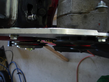
A bit hard to see, but this is looking down on all 3 pulleys. You can see the red laser light on the centre of all 3. I think they are lined up pretty well. Now to measure and hit the local NAPA for a drive belt.