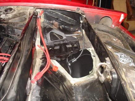
I've run a +ve cable and a ground cable from the battery area. Still a little rust to fix up in the side of the trunk....one of those jobs for later.
The battery cable runs under the body and over the shock tower area. It is clamped along the top of the engine compartment along the side. This cable runs to the starter solenoid. The other end will be shown later, with the other wires that are in the solenoid area.
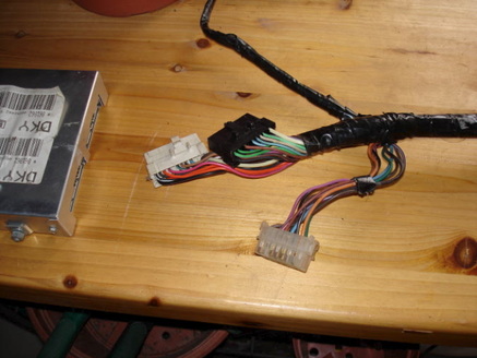
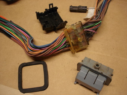
Now the fun starts! The metal box on the left is the computer from the car, normally mounted to the firewall in the passenger compartment. Since I'm not using fuel injection, I don't need the computer. Since I don't need the computer, I don't need the 30-40 wires that connect to it. That makes a lot less wiring to run through the firewall and into the engine area. It also neatens things up and saves a bit more weight. The black and white connectors, near the computer, are the ones that normally plug into the computer. I'm cutting those off and stripping out all of those wires. The other white connector (bottom of the screen) connects to a harness under the centre console in the car and joins to the instrument panel area; that one I have to keep.
I've peeled the tape off the harness in preparation for it's lightening. The large grey/black thing on the harness is where it passes through the firewall. This thing clamps on the harness, and then is filled with sort of hot-melt glue. A bit of a pain to take it all off, but once I remove that block, I can strip out the excess wires and there will be only about 8 wires to pass through the firewall, so I won't need that giant block.
You can see what it looks like with the plastic parts removed; there is the block of hot-melt glue left on the harness. Note that the wires are not connected at all in this area, they just were encapsulated in the glue/plastic parts. Now it is just a matter of picking apart the glue block to expose the wires. A heat gun helps to soften it.
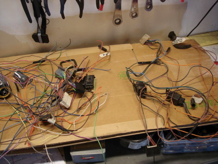
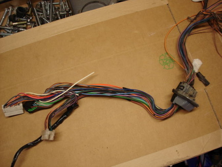
So the block is all removed, the connectors to the computer snipped off, and all of the wires that were going to the computer have been removed. The bundle on the left is all of the wires/connectors that are not needed. The wire bundle on the right is what is left that will go into the car. Much simplified!
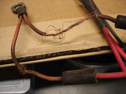
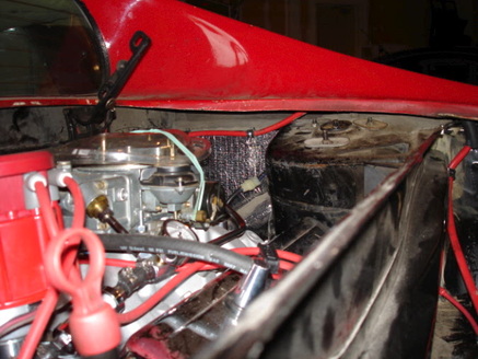
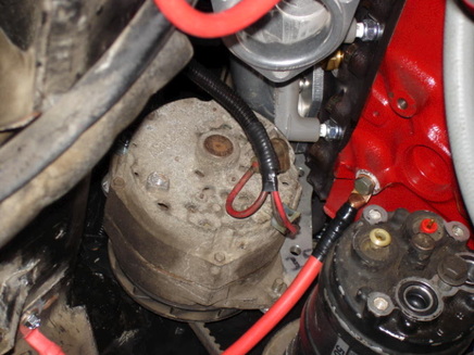
The Fiero's use fusible link wire in the engine compartment (modern cars use fusible links that look like a thin piece of sheet metal). There is nothing wrong with fusible link wire unless you run it very close to the exhaust, like they did with the '84 Fiero. This is what it ends up looking like. There are 2 pieces of fusible link wire running off this connector that goes on the starter solenoid. Obviously these have to be replaced. Because of the arrangement of the starter/exhaust with the V8 this will be farther away from the heat of the exhaust so it should not deteriorate like this. Then again, it did last 25 years so that isn't too bad.
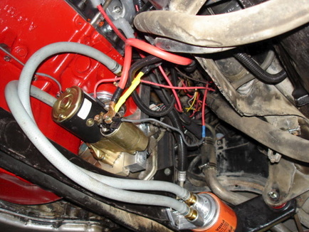
This is a view looking up at the starter motor area (very nice to have the car up on a lift to work on this stuff). The large red wire is the main +ve battery cable to the starter solenoid. The wire with the yellow heat-shrink on it takes the battery power up into the main harness for the rest of the car, and also a lead runs off to the alternator. The thin black wire is a new piece of fusible link wire, also taking power up into the main harness.
This is the other end of the engine, showing the alternator wiring. Also you can see a ground cable I added from the engine block to the frame of the car. The #1 spark plug is very close to the alternator, but there is enough room to get it and the wire on and off. But remember how close this is, as it will cause a minor concern later.
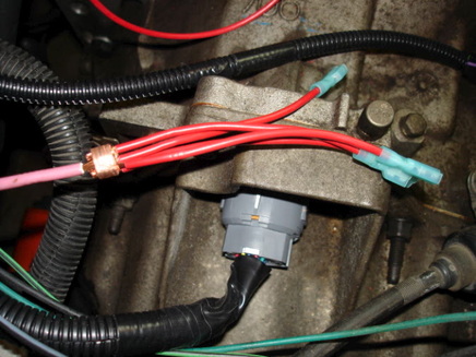
This is just showing how I join 4 wires into 1. The large pink wire is the "ignition" wire. This is the wire that carries 12 volts when the key is in the "ignition" or "on" position, and also when it is in the "start" position. Since I need power to the ignition box (for spark), the transmission controller box, the electric choke on the carburetor, and also to the fuel pump relay, I've tapped all 4 from this one source. I use a small piece of copper, cut from the left-over tubing that I used for the cooling system, to crimp things together. Then it is soldered and wrapped with electrical tape or shrink-wrap. Oh, the large connector just below this is the main transmission control plug leading back to the transmission control box. This box will be mounted in the car, where the computer used to be.
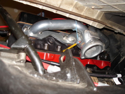
If you can figure out what I'm doing here, you win a prize. No, I'm not making my own spark plug from an old pencil, but the pencil is sticking into the #6 spark plug hole in the cylinder head. Here is what is going on:
To set the timing on a engine, you set the engine so the #1 piston is at top-dead-centre (TDC) on it's compression stroke. Then you make sure the rotor in the distributor is pointing at the #1 spark plug lead and everything is fine and dandy. So how do you make sure the #1 cylinder is at TDC? There are a few ways, one of which is to take the spark plug out, put your finger over the spark plug hole in the head, crank the engine over with the starter motor, and feel when the pressure blows your finger out. No problem so far, this all works fine with this installation. Then you are somewhere near TDC on the compression stroke, so you line up the timing marks on the main engine pulley (the harmonic balancer) with a stationary mark on the front of the engine. Problem here! With this installation, you can't see the front of the engine since it is right up against the frame rail and covered by various things on all sides. So another thing to do is to put something into the spark plug hole and feel when the piston is at the top. Remember how close the #1 spark plug is to the alternator? Very difficult to get something in there. The way a Chevy engine works is that when the #1 cylinder is at TDC compression, the #6 cylinder is at TDC exhaust. So once we have the #1 cylinder near TDC compression, we can make sure piston #6 is at TDC and everything will work out fine. There was not enough room here to get a dial indicator in the cylinder, so this is what I came up with. One end of the pencil is resting on the top of the piston (#6, but #1 would work just as well if there was good access to it). The pencil is pivoting against the inside of the spark plug hole, and the rubber band loading it against piston. So as the engine is rotated slowly, the outer end of the pencil will go down as the piston goes up. I rotated it while watching the pencil and stopped when it was at the lowest point. Very low-tech, but it works. It might not be dead on, but it should be within a degree or 2.
It's stuff like this that takes a long time to figure out, but doesn't show much progress (kind of like most of the wiring). Of course if I was thinking ahead I would have set things up before installing the engine, and put some timing marks where they can be seen.
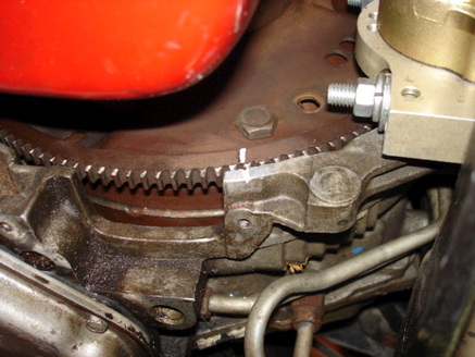
Since you can't see the conventional timing marks with this installation, here is one place to put them. This is a shot from underneath the engine/transmission, looking at the flexplate (remember this being machined a few pages ago?). I filed a small mark in the transmission housing and put some white paint in it. I also made a white mark on the flexplate, with the engine still set at TDC compression on #1 cylinder. The only problem is that to set the timing you have to be under the car with the timing light, with the engine running; should be fun setting the timing. But this really only has to be done once, so it shouldn't be too bad. For those that are following all this, I only need this one mark, since I use a timing light that lets you set the timing on it, and then basically "zero" the timing marks. Normally you would see several marks, for TDC and maybe every 2 or 5 degrees before this up to 15 or 20 degrees.
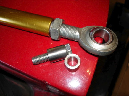
I forgot about the last engine mount. It's more of a steady-rod, at the back of the engine, going from the frame to the cylinder head. The thread in the cylinder head is smaller than the holes in the rod, so I made some spacers. I actually made these a while ago and forgot about them.
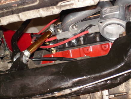
You can see the rod installed here. Goes from the mount I welded onto the frame cradle (seems like ages ago) up to the back of the cylinder head.